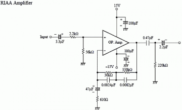

I designed this circuit to use 12V computer fans, as these are now very easy to get cheaply. We try to come to see this circuit use op-amp IC LM741, be usable easily and, It can change R1,R2 for fix the expansion ratio has of the circuit with.

More than the frequency Fundamental 30 dB, for output be sawtooth wave form for use in sound of music way system Electronic design will use the circuit filters three rank frequency.īy have 3 dB you slopes can use Op-amp IC number LM741 or number LF351it will meet the frequency well. It will use to build Harmonic at 3 of 130.81 frequency have the value at least.
#Persamaan ic 741 generator
Persamaan Ic Ua 741 Cn Generator Signal Circuitīy IC1, D1, D2, C1, C2 and R5 build be sound generator signal circuit then export come to way pin 6 of IC1a come to reach at pin 3 (Noninverting) of IC1b.įor do fining level has signal then signal to come out the way pin 7 of IC1b which will have flowing through comes in at pin B of Q1 for do something bias give Q1 bias. The principle works to are while still no press switch S1 will still have no the loud sound comes out from a loudspeaker SP1.

The circuit shown here uses a 741 with positive feedback via R5,R6 and R7 for fast switching.Voltage dividers R8 and r9 set the DC input voltage to the non-inverting input terminal to half the supply voltage.The amount of positive feedback depends on the ratio of R6 and r7.the larger the ratio,the smaller will be the hysterisis shown by the circuit.Potentiometer r2 sets the DC voltage to the inverting input terminal and thus sets the threshold voltage at which the signal will trigger the circuit.The input signal can be applied to either of the two input terminals.Īnd access to the AF OUT to be applied to various tasks.VR1 is adjusted by the strength of the output signal sent to the AF OUT. The VR1 is adjusted reduce the growth of low-frequency (BASS) and VR2 is increasing rate of growth of the frequency High (TREBLE). Q1 is the e-limit circuit fault Peter Low Power Amplifier stand out in E via C2 to the region to adjust the bass treble. The audio input is entered through the C1 coupling to the input signal to the Q1 growth signal by R1 and R2 divide the voltage. The power supply circuit is used from 12-24 volt and Shine Power consumption is 10 mA. This helps the smooth bass voice circuit and a rate increase reduction of the signal at 18 dB.
#Persamaan ic 741 full
The micro ampere meter shown here is basically a DC millivolt meter.The circuit gives full scale deflection for 0.1V input.The current to be measured is passed through a known resistance R and the voltage drop across it is measured.Here the IC 1 uA 741 op-amp is wired as a non inverting amplifier. Persamaan Ic Ua 741 Cn Full Scale Deflection Until the pin 3 of IC1 is low pressure over the two legs a little.LED1 off, it will be.If we adjust VR1 compared to the pressure they can pretend to know the scale at the VR1.Voltmeter can not be used to measure the pressure of the alternating current (ACV) home. Persamaan Ic Ua 741 Cn Full Scale Deflection.Persamaan Ic Ua 741 Cn Generator Signal Circuit.


 0 kommentar(er)
